![]()
![]()
The notes are included below. Click on the reference numbers for easy access.
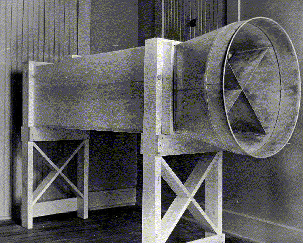
As a result, biographers of the Wright brothers tend to breeze past the wind tunnel on their way to the exciting stuff just a little further down the timeline. They dutifully relate the necessary facts, telling us the wind tunnel and its balances were deceptively crude. The tunnel was little more than a pine box and the balances were fashioned from worn out hacksaw blades and discarded bicycle spokes. Yet the data gleaned from the tests was remarkably accurate, despite the homespun appearance of the instruments. The Wright wind tunnel experiments marked the first time that anyone had measured the lift and drag produced by various wing shapes with sufficient accuracy for them to be of any use in aircraft design. And with that, the biographers leave the Wright's laboratory work and get back to the flying.
|
Click on a
photo or illustration to enlarge it.
|
|||
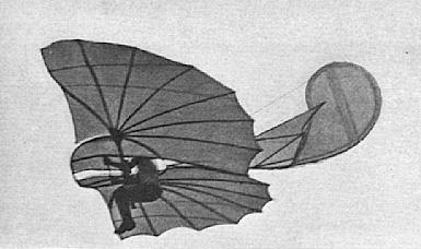
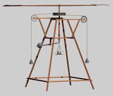
From Enthusiasts to ScientistsThis is unfortunate because the wind tunnel experiments are the stuff that world-class aviation history is made of. The Wrights drew back the curtain on the elusive laws of physics that allow us to fly and exposed them in neat rows of numbers. And more important than the numbers themselves are what measurements the brothers chose to make. Wright biographers completely miss the wind tunnel story when they tell us that the Wrights were the first to make accurate measurements. Several investigators prior to Wilbur and Orville had conducted experiments with wing shapes that produced reasonably good numbers. But these earlier pioneers had an incomplete understanding of the dynamics of a wing in flight. Consequently, the forces they chose to measure or how they interpreted their data rendered their efforts less useful than they might have been. Furthermore, no one before Wilbur and Orville checked their data against the performance of an aircraft in flight. The Wrights were the first to verify laboratory results with actual flight tests. If they had never done anything beyond compiling and verifying their lift and drag tables, we would still remember the Wright brothers for their substantive contribution to the development of aviation. The wind tunnel also marked an important change in the intellectual posture of the Wright brothers. Prior to September 1901, they were more enthusiasts than scientists. They were well read in aeronautical science, but naïve in its application. The biographers tell you that the Wrights used Otto Lilienthal's lift tables to design their first two gliders. Lilienthal was the world's first successful glider pilot, having designed and flown his own gliders between 1891 and 1896. He used a whirling arm apparatus to measure the forces on a wing. The Wrights began to suspect that Lilenthal was wrong when their gliders failed to develop the predicted lift. What the biographers miss is that the Wrights applied these tables incorrectly, using lift data for Lilienthal's wings to predict the performance of their own wing designs, even though the shapes differed markedly. That being so, it's not surprising that the performance of the Wright's early gliders was disappointing. The brothers first attempted to fly in 1900, making a pilgrimage to the sand dunes near Kitty Hawk, North Carolina where the winds were stronger and the ground softer than in their hometown of Dayton, Ohio. They brought with them a biplane glider with a wingspan of 17-1/2 feet and a parabolic camber of 1/20. They had designed this glider interpolating Lilienthal's data for his standard arc-shaped 1/12 cambers. When the 1900 glider failed to produce the expected lift, the brothers increased the wingspan of their 1901 glider to 22 feet and the camber to 1/12, but retained the parabolic shape. They also increased the chord to make wide wings, unaware that a low aspect ratio -- the ratio of wingspan (length) to chord (width) -- can also reduce lift and cause control problems. As a result the 1901 glider performed worse than the 1900 in many respects. The brothers rigged the glider with a complex system of wires and ropes that reduced the camber to 1/19. This salvaged the 1901 flying season, allowing them to make a few manned flights. But the glider's performance was not what they had hoped. Wilbur was so dejected during the train ride back home that he commented that he did not believe that man would fly in their lifetimes, possibly not for another thousand years. In fact, Wilbur and Orville came very close to abandoning their aeronautical ambitions. But waiting for Wilbur when he arrived home in Dayton, Ohio was an invitation from Octave Chanute to come to Chicago to speak to the Western Society of Engineers about their gliding experiments. Chanute was a highly respected civil engineer, an aeronautical visionary, and a prolific correspondent with many experimenters in the aviation field. Wilbur was flattered by Chanute's invitation, but it presented a quandary. Neither Wilbur nor Orville considered that their experiments to date were worth the attention of such a learned body, even though they had been able to make about 40 respectable glides on their 1901 glider. However, they had done one thing that might be of interest to these engineers. They were the first aeronautical investigators ever to measure the performance of their aircraft in actual flight and compare the results with laboratory data -- in this case, Lilienthal's data. Their quandary was that the flight performance did not match the data and they had absolutely no idea how to explain this discrepancy except a hunch that Lilienthal's tables were wrong. Wilbur decided to say as much in his speech. We don't know exactly what he said -- he rewrote the speech for publication after he was well along with his wind tunnel experiments and is reported to have softened the things he said about Lilienthal's work. He may have also changed other sections since his understanding of aerodynamics matured quickly after his speech. But whatever he did say, it stirred up a good deal of interest. Chanute reported to Wilbur that there were many requests for copies of his speech. It seemed to stir something in Wilbur and Orville, too. Just before Wilbur left to deliver his speech, he and Orville experimented with a crude wind tunnel made from a soapbox. The experiments seemed to satisfy them that Lilienthal's tables were indeed wrong and Wilbur was safe in saying so to the Western Society of Engineers. When Wilbur returned from giving the speech, the brothers devised another experiment. They mounted a wheel horizontally on a bicycle, then attached a flat plate and a miniature wing or airfoil to the wheel. These were positioned so that when the bicycle was pedaled fast enough to create a wind blowing over the wheel, the drag on the plate was balanced against the lift generated by the wing. This too indicated that there were problems with Lilienthal's tables, but the apparatus was imprecise. In order to get the data they needed to build flying machines, they would have to devise a precision instrument. They decided to build a wind tunnel and balances.1 Once the Wrights determined to collect their own lift and drag information, there was a phenomenal change in the brothers over the span of a few months. They quickly put their inexperience behind them and carefully thought through the aerodynamic forces on a wing in flight, defining in their own minds what they should measure. Once they had made these measurements, they learned to apply their new data properly to aircraft design and came to a better understanding of the relationship between lift, drag, and wing shapes than anyone else in their field. In September 1901, they were part-time investigators, badly discouraged by their failures and hamstrung by their lack of experience and understanding. By January of 1902, they were creative and confident scientists pushing back the frontiers of aeronautics.2
|
|
|||
Wright AnglesTo understand the difficulty of the problem the Wrights faced in September 1901 and the genius it took to solve it, you need to understand the mathematics behind the pine box and the used hacksaw blades that made up the tunnel and balances. If you are one of the mathematically challenged, don't despair -- the logic behind the formulae is easy to grasp. In fact, you may have an advantage over someone educated in aeronautics. The methods used to analyze lift and drag today are different from what the Wright brothers used. Modern aeronautics looks at the forces in play on a wing as vectors. The Wright brothers and their contemporaries thought in terms of angles. Today, we use a form of calculus called vector analysis to study these forces; the Wright brothers used simple trigonometry.3 Because of this, contemporary aeronautical engineers often react by labeling these older methods as wrong or incomplete. In their historical context, however, they were the best methods available at the time.
|
||||
|
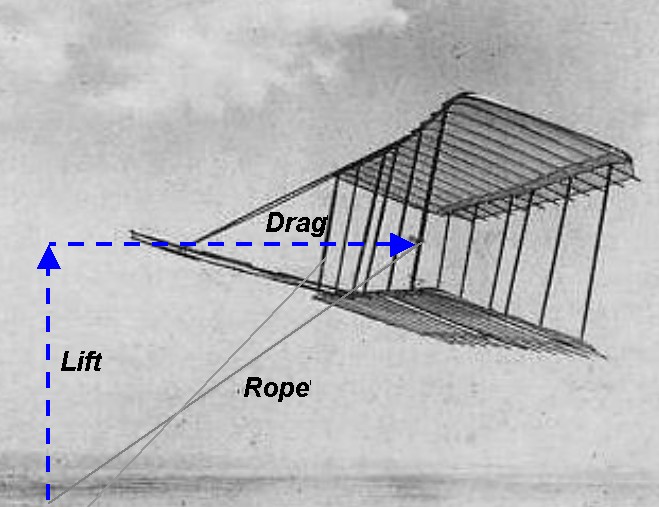
This isn't to say that the Wright's analysis of lift and drag was simplistic. In a letter to Octave Chanute on January 5, 1902, Wilbur carefully defines the forces in play on a wing in flight, taking into account the angle of attack (which he refers to as the angle of incidence), the path of flight, and the wind relative to the motion of the aircraft. "It has been a problem for me, ever since we began our experiments...what pressures we should attempt to measure and what should be the basis of our table." He wisely decides to make those measurements that will be most useful to him in analyzing actual flights. "...true lift and true drift...are alone to be considered in calculating glides." True lift Wilbur defines as the pressure or force directly opposed to gravity and true drift is a force perpendicular to it -- what we now call drag. Lilienthal's tables, he notes, do not contain numbers that are immediately useful. Lilienthal based his table on the pressure perpendicular to the chord (the normal force) and the portion of that pressure that increases or retards the forward motion of the aircraft (the tangential force).4 Neither could be used directly to design an airplane. "...normal and tangential [must be reduced] into vertical and horizontal components, which is inconvenient and a waste of time," Wilbur wrote. It was a bold -- maybe even brash -- statement. Lilienthal's astounding success as a glider designer and pilot in the 1890s had made his scientific writings central to aeronautics. His emphasis on the tangential had led many investigators to conclude it was the key to soaring flight.5 But just five months after applying these tables incorrectly to the design of their 1901 glider, Wilbur now understands Lilienthal's tables and their limitations. The tangential, he knows, is a red herring. The Wright brothers will measure lift and drift. By doing so, they accomplished in a few months what had eluded other scientists for a century.
|
 Wilbur included this diagram of the forces on a wing in flight with his letter to Chanute on January 5, 1902. After nearly four months of intensive reading and experimenting, he had brought himself to an intimate understanding of these forces just so he could cut through the Gordian knot of vectors and angles. He decided was really important was lift parallel to gravity and drift or drag parallel to the horizontal wind (highlighted in blue). His and Orville’s balances measured the rectangular pressure - lift perpendicular to the relative wind - and drift parallel to it (highlighted in red). In the wind tunnel, the relative wind and the horizontal wind coincided. Consequently, the lift was the same as the rectangular pressure. |
|||
|
The brothers looked on these forces of lift and drift as the legs of a right triangle. This was the same triangle that Sir George Cayley drew in 1799 when he first conceived of the idea of a fixed-wing aircraft. Drift (or drag) was the base, lift was the side. According to the Pythagorean theorem that was drilled into most of us in high school, all the parts of that triangle -- base, side, hypotenuse, and the angles between them -- bear a distinct mathematical relationship to one another. By using simple trigonometry and ratios called sines, cosines, and tangents, the Wrights could find any part of the lift-drag triangle as long as they knew the magnitude of one part and one of the angles between the hypotenuse and another part. They had used trigonometry to measure the performance of their glider
when they flew them in Kitty Hawk. The brothers tied off the controls and
flew each of the gliders as kites, attaching tether ropes to the leading
outboard struts. The tether ropes, they noticed, stretched up at an angle.
This angle was the result of lift and drag. The lower the lift or the
higher the drag, the greater the angle of the rope as measured from the
vertical. The rope was, in effect, the hypotenuse of the lift-drag
triangle. Using an ordinary spring scale, they measured the tension on the
ropes (
* * Once they had found these numbers for lift and drag, the Wright
brothers plugged them into established formulae to determine whether their
wings were developing the expected lift and drag. These lift and drag
formulae had their beginnings in the work of John Smeaton, an English
engineer that studied the action of water wheels and windmills. Smeaton
observed that when the wind blew against a sail, energy was transferred in
the form of pressure on the sail. The amount of pressure generated was
proportional to the size of the sail (
* * *
|
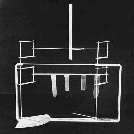
 Cayley sketched the first scientifically designed fixed-wing aircraft on this silver disc. On the back, he diagramed the forces of lift and drag, forming a right triangle.
|
|||
|
Later investigators noticed that this pressure varied with the angle of attack -- the angle at which the sail met the wind. Cayley realized that this was because only part of the pressure was being converted to lift. The remainder became drag (or "resistance" as it was called then). The ratio between lift and drag changed with the angle of attack. For aeronautics, Smeaton's formula needed another multiplier, a coefficient of lift. This determined what portion of the kinetic energy in the wind was converted to lift the wing at a given angle of attack. As it came down to the Wright brothers, the formula looked like this:
Where: * The portion of the pressure that became drag was expressed in a similar formula:
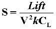
Where: * When they first designed their gliders, Wilbur and Orville had applied a little algebra to the lift equation to rearrange the terms so they could calculate the optimum size of the wing. They were experienced craftsmen with both wood and metal and could make a good guess at what the completed glider would weigh. They added this to their own body weight to arrive at the minimum amount of lift the wings would have to generate. They also knew the approximate velocity of the winds they considered safe to fly -- not over 20 miles per hour. They plugged these values into this formula to find the surface area of the wings:
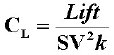
As mentioned previously, the Wright brothers initially obtained their lift and drag coefficients from tables compiled by Otto Lilienthal. When the Wrights' 1900 and 1901 gliders did not performed as predicted, they suspected that either Lilienthal's tables or Smeaton's coefficient were incorrect. In the early years of the twentieth century, many different scientists including members of the U.S. Weather Bureau and Samuel Langley of the Smithsonian Institution had begun to question Smeaton's accuracy. Octave Chanute, who corresponded regularly with Wilbur Wright, had collected some 40 possible values for k from 0.0027 to 0.0049. Lilienthal had used Smeaton's coefficient in calculating the lift and drag coefficients in his tables. Once he had analyzed the data he gleaned from his whirling arm to find the lift, and he rearranged the lift formula in this fashion:
|
 Sir George Cayley performed the first aerodynamic experiments with lifting surfaces using a primitive whirling arm apparatus. |
|||
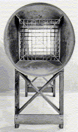
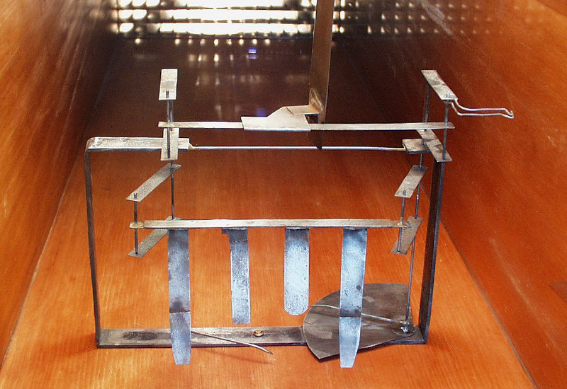
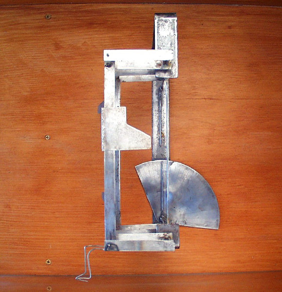
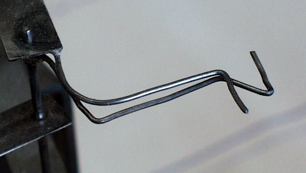
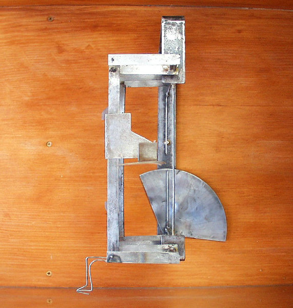
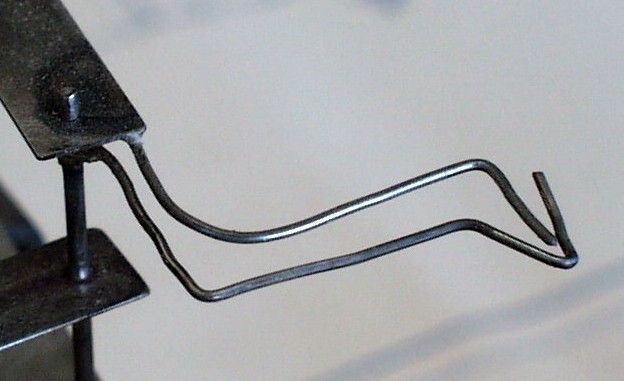
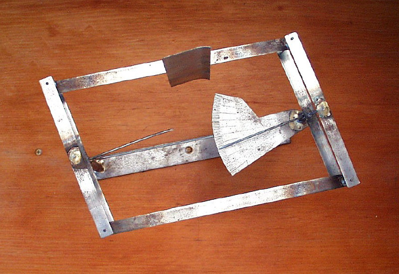
Balancing ActThey designed "lift" and "drift" balances to make the necessary measurements for these tasks. Both instruments balanced one force against another, measuring the ratio of the forces. The lift balance, for example, pitted the force of lift generated by an airfoil against the pressure on a plate the same size as the airfoil.6 At first this plate was a single sheet of 6 square inches, but the Wrights found this caused eddies in the wind flowing through the tunnel and interfered with the measurements. So they cut the plate up into several " drag fingers." Although it appeared crude, the lift balance was a sophisticated
mechanical analog of the forces in play on a wing, designed to measure the
coefficient of lift ( Mechanically and mathematically, here's what was happening. The lift
generated by the airfoil pulled the arms of the balance to the side, while
the drag on the airfoil and the pressure on the drag fingers pulled it
back. (The two forces acted at 90 degrees to one another.) The sine of the
first angle (
The surface area (
It was an ingenious bit of scientific instrument design. The lift
balance was able to measure the coefficient of lift directly simply by
taking the sine of the second angle ( |
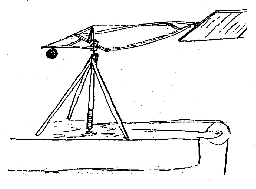
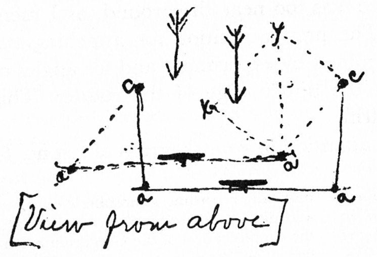 In a letter dated October 24, 1901, Wilbur explained to Octave Chanute how the lift balance he and Orville had designed would work. Wilbur’s diagram above, which was included with the letter, shows the lower arms of the balance - the upper arms and the air foil are left to your imagination: "The arms ac bear the crosspiece aa and with the imaginary line cc form a parallelogram with the corners cc fixed and the arms ac turning on these points. The wind strikes the [drag fingers] (indicated by the short black lines) at an angle of 90 degrees in all positions of arms ac. Now if the lift [generated by an air foil on the upper arms is] transmitted to the point a and applied at right angles to arms ac, the [drag fingers] will [move] to the position indicated by the dotted lines and the pressure exerted will be as ax is to ay, i.e. the lift will be equal to the sine of the angle aca."
|
|||
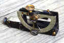
 1. With the wind off, the Wright brothers mounted an airfoil on the upper arm and adjusted it to the desired angle of attack. They most probably used a steel rule with a protractor head - a common set-up tool in machine shops - to set this angle. |
 2. The Wrights turned the wind on and the lift generated by the air foil pulled the upper arm sideways while the drag on the air foil and the drag on the fingers pulled it back. This moved the pointed over the scale. Note that the wire indicators are no longer aligned. |
 3. With the wind still on, the Wrights adjusted the upper arms until the wire indicators were aligned again. This subtracted the air foil drag from the forces that moved the pointer. The new angle indicated on the scale was the result of lift balanced against the drag on the fingers. |
|
|
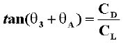
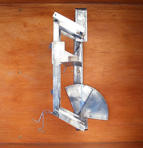
The drift balance9 measured the ratio of the coefficient of drag to the
coefficient of lift (
|
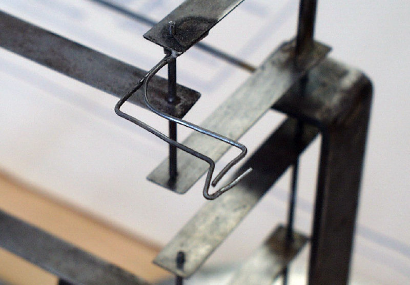
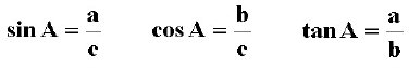
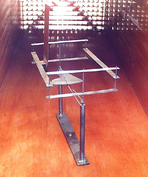 Our replica of the drift balance mounted in the wind tunnel.
|
|||
| This enabled them to build a table of coefficients for many different
airfoils at varying angles of attack. By plotting the lift and the drag of
each foil against the angles of attack, they were able to see and compare
the efficiency of the wing shapes. The Wrights were not just looking for a
wing that would produce enough lift to buoy them in the air; they wanted
to find an efficient wing shape, one that would produce the most lift and
the least drag. They were perhaps the first to understand that a high
lift-to-drag ratio would result in a shallow gliding angle and extend
their flights. They didn't just want to fly; they planned to soar.
|
 2. When that was done they simply turned on the wind and read the scale. The added the angle of attack to the angle indicated on the scale. |
|||
Close EnoughThe Wright brothers tested over 200 airfoils and prepared complete tables for about four dozen. But there was one more step to take before they had all the numbers they needed to design an aircraft. As previously mentioned, Wilbur and Orville had measured the lift and the drag produced by their 1901 glider. They consulted the table they had prepared with the airfoil that corresponded to the shape of the wing in this glider. Once again, they used a little algebra to rearrange the standard lift formula to calculate the coefficient of air pressure:
They checked their calculation by rearranging the drag formula:
From this, they determined the coefficient of air pressure to be
0.0033, over 40 per cent off from Smeaton's value of 0.0054.10 Today, the
accepted value used to design low speed aircraft is 0.00339 and the value
used for high-speed aircraft under normal conditions is .0327. The Wright
brothers were off by less than one ten-thousandth. |
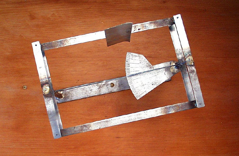
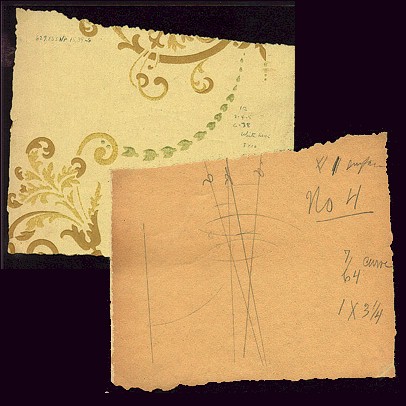 As the Wrights accumulated wind tunnel data, they recorded their experiments on scraps of wallpaper.
|
|||
|
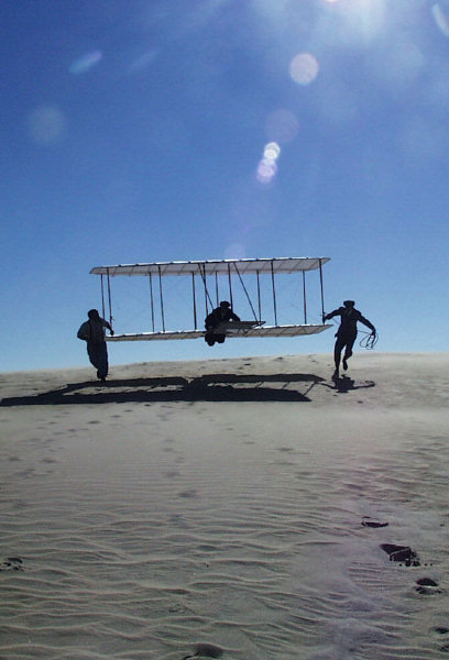
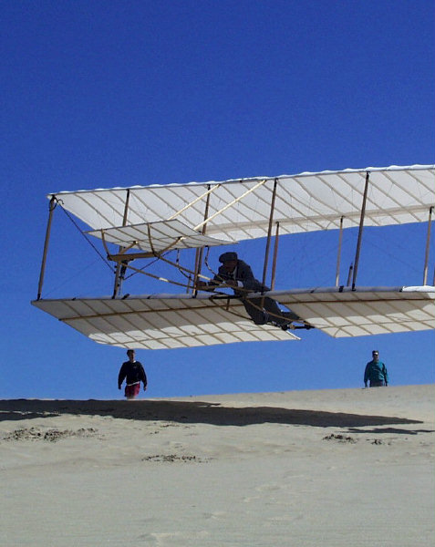
The true test of their work, however, was how it effected their aircraft. The 1902 Wright glider was the first flying machine the Wrights designed using their own data, and it was to first to actually produce the predicted lift. The 1902 glider not only lifted a pilot into the air, it also responded well to its controls and descended at a shallow angle, extending their glides to 600 feet or more -- proving the value of a high lift/drag ratio. This glider became the test bed for a revolutionary new control system and the basis for the Wright patent, the grandfather patent of the airplane. The brothers made over 2000 glides in this machine, honing their pilot skills to a fine pitch. When they finally climbed aboard their powered Flyer on December 17, 1903, they were already the most experienced pilots in aviation -- and two of the world's most accomplished scientists. |
 The end result of all this measuring was the 1902 Wright Glider, a remarkable aircraft that became the basis for the grandfather patent of the airplane. Shown above is our replica of the 1902 glider as we repeat some of the Wrights unmanned flight tests to determine lift and drag. |
|||
Notes:1The wind tunnel had been invented in England in 1871by Francis Wenham and John Browning, who used it to study both wing camber and aspect ratio. Over the next three decades, several other experimenters used it for aeronautical research, mostly in Europe. The 1901 Wright wind tunnel was the second or the third in America. 2It's telling that the Wright brothers built their wind tunnel and balances and began collecting data before they had a clear understanding of aerodynamic forces or the measurements they wanted to make. Prior to the January 1902, the terms that Wilbur uses to describe aeronautical forces aren't clearly defined in his mind, and he makes conflicting statements. In all fairness to Wilbur, this is not just a measure of his initial confusion but also the confusion that existed in the field at the time. The components of lift and drag were hotly debated, terms had various meanings depending on how they were used and who was using them. But it's also a good example of how the Wright brothers best worked through a problem. They were "hands on" investigators. To figure out what they were going to measure, they started making measurements. |
||||
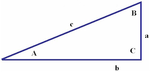
3If you are unfamiliar with trigonometry, here's a quick primer.
"Trig" depends on ratios called sines, cosines, and
tangents --
one side of a right triangle divided by another. For a triangle with sides
a, b, and c and angles A, B, and C as shown, the ratios are as follows:
These ratios are different for each angle but remain constant with size -- as long as the angles between the sides remain the same, the ratios are unchanged same no matter what the size of the triangle. Consequently, if you know the magnitude of just one side and one angle (other than the right angle), you can calculate the other two sides by looking up the sine, cosine, and tangent ratios of the known angle and multiplying the appropriate ratio times the known side.
|
||||
|
4"Normal" was used in the Wright's day much the same way we
use "perpendicular" today. The normal force was lift
perpendicular to the wing chord. True lift was parallel to the force of
gravity and perpendicular to the horizon. Because the wing usually flew at
an angle of incidence (our modern angle of attack) that was not parallel
to the horizon, the normal force was often at an angle to true lift and
the force of gravity. When added up, the forces on the wing resolved
themselves into the resultant pressure. Many aeronautical investigators
considered that this pressure must correspond with true lift, but Wilbur
thought it must be angled slightly forward of lift to compensate for head
resistance -- what we now call parasitic drag. The tangential
was
calculated from the angle between the resultant pressure and the normal
force (
5In the Wilbur and Orville's time, aeronautical investigators studied two distinct types of flight -- soaring flight and dynamic flight (what we now refer to as gliding flight and powered flight). Scientists considered both types to be similar, but the forces in play and the mathematics used to analyze them were somewhat different. Wilbur and Orville were squarely in the soaring camp in 1901. In fact, there is no real evidence to suggest that they planned to attempt dynamic flight at this time, although Wilbur sometimes discussed its theory with Chanute. But they never performed a single experiment that had a direct application to dynamic flight until late October 1902. Their 1901 wind tunnel tests, the forces they measured, and the tables they compiled were all designed to solve problems in soaring flight. One example of this is the importance they placed in the lift/drag ratio. This number was central to the performance of a glider -- the higher the ratio (more lift, less drag), the better the gliding angle irregardless of the weight of the glider and its pilot. The Wrights were perhaps the first to understand this. 6Initially, the brothers cut the plate into five fingers. But when they
mounted the fingers on the balance, they found one of the fingers near the
frame was affected by eddies in the wind coming off the frame. They
removed this finger, cut it in two and soldered the parts to two of the
remaining fingers. This accounts for the seemingly random length of the
fingers. In their final tests, the Wrights used some air foils with 8
square inches of surface area -- a third more than the drag fingers. To
compensate, they added another third of the sine of
7Each balance had two pointers, but just one was used to indicate the angle on the scale. The second pointer balanced the force of the wind hitting the first pointer and kept it from affecting the measurement. 8Wilbur's original estimate of the wind speed in the tunnel was 40 feet per second, or about 27 miles per hour. Later, his estimate was revised downward to 25 miles per hour. This velocity would have been very difficult to achieve given the equipment the Wrights were using. When we reproduced the wind tunnel and duplicated the experiments, we used a four-bladed balanced fan running within 10 percent of its maximum safe speed. This produced airflow in the tunnel of 20.3 miles per hour. The Wrights were using a homemade fan with just two blades. It was not dynamically balanced and could not have run for long periods of time at speeds in excess of ours without flying apart. Even if it held together, the vibration at high speeds would have interfered with the experiments. While he was engaged in the wind tunnel tests, Wilbur commented to Octave Chanute that the Richards anemometer they had used at Kitty Hawk (and probably used for the wind tunnel tests) recorded high. Taking all this into account, it's likely that the wind blowing through the Wright's tunnel was less that 20 mph. 9The Wrights called this their "tangential measuring machine." Because they rotated the entire balance, including the scale, the pointer indicated an angle that expressed the ratio of lift to drift minus the angle of incidence (attack). This was essentially the angle used to calculate Lilienthal's tangential force. To get the ratio of true lift to true drift, they had to add the angle of incidence to the angle indicated on the pointer. They sometimes called this the gliding angle, not to be confused with the modern definition of the term, which describes the angle at which a glider descends through the relative wind. 10There is no written record that the Wright brothers actually made these calculations to establish the value of the coefficient of pressure. Wilbur had already written Chanute that he suspected the answer was .0033; this was the number that best explained the lift and drag he and Orville had measured when flying their 1901 glider at Kitty Hawk. But with the wind tunnel experiments, the Wright brothers had developed into world-class scientists. It's inconceivable that they wouldn't have taken this final step to confirm their hunch. |
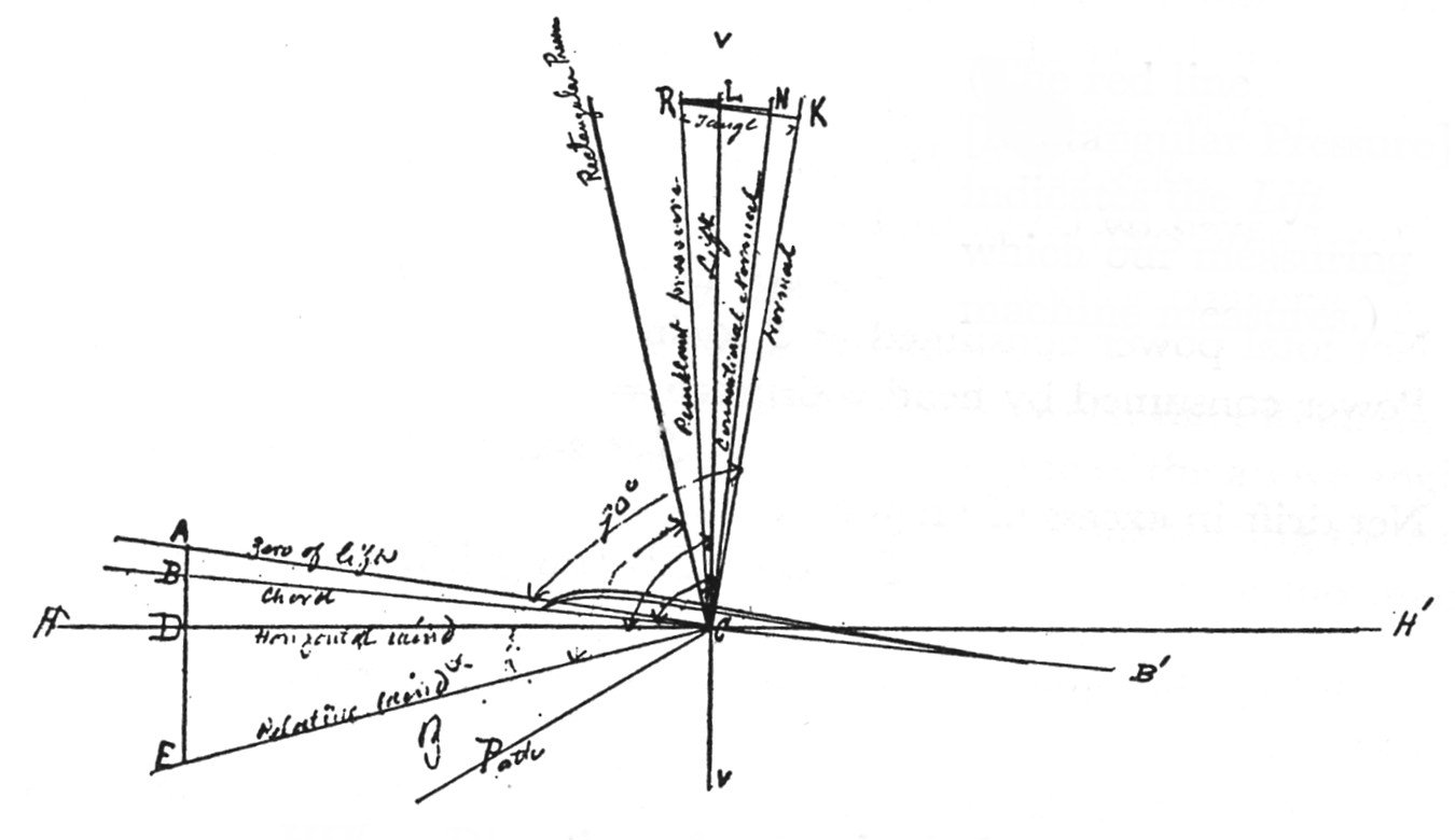 Wilbur's diagram of aerodynamic forces on a wing in flight. |
|||
![]()
![]()