WRIGHT BROTHERS Aeroplane
Company
![]()
![]()
![]()
![]() elow are several "three-views" (top, front, and side
elevations) of Wright airplanes. The drawings are shown small on this page, but
you can download much larger and more detailed copies of the same drawings.
Right click on the drawing you want and choose "Save Target
As" (in Explorer) or "Save Link As" (in Navigator) from the
pop-up menu that appears. Save the drawing file to a folder on your hard drive.
The drawings are large files -- some as much as 700K -- so they may take a while
to download depending on the speed of your modem.
elow are several "three-views" (top, front, and side
elevations) of Wright airplanes. The drawings are shown small on this page, but
you can download much larger and more detailed copies of the same drawings.
Right click on the drawing you want and choose "Save Target
As" (in Explorer) or "Save Link As" (in Navigator) from the
pop-up menu that appears. Save the drawing file to a folder on your hard drive.
The drawings are large files -- some as much as 700K -- so they may take a while
to download depending on the speed of your modem.
Once you have downloaded them, you can either view them on your computer or print out a large copy. They have been scanned at a sufficient dpi resolution to print out a crisp image on an 11" x 17" sheet of paper. If you don't have a printer that will handle a sheet that big, trying printing out the top, front and side views individually on ordinary 8-1/2" x 11" sheets. To do this, make several copies of the drawing file, then crop the drawing in a graphics program such as Photo Editor, Photo Deluxe, or PhotoShop so you have individual views.
These drawings were made many years ago by Library of Congress draftsmen for the purpose of comparing the Wright airplanes and tracing their development. For that reason, most of them lack measurements. If you wish to use these drawings to make scale models, you'll need to add your own dimensions. This isn't a difficult chore. Let's say you want to make a model of the 1903 Wright Flyer 1. First choose one measurement -- most model-makers start with the wingspan, say 12 inches. You measure the wings on the print-out of the drawing and find they measure 8 inches. Divide the wingspan of the drawing into the wingspan of the model. 12 divided by 8 equals 1.5. This is your "enlargement factor." From this point on, you can measure any part on the drawing, multiply it by the enlargement factor and arrive at the size of the part on the model. For example, if the struts measure 4 inches long on the drawing, you should make them 6 inches long on your model -- 4 times 1.5 equals 6.
Remember, you must calculate your own enlargement factor for each drawing. It will differ from drawing to drawing depending on how you print it out.
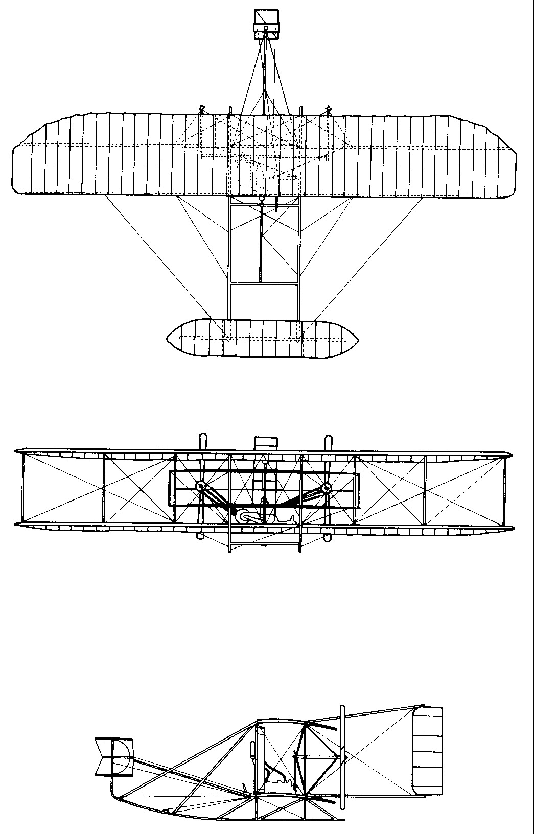
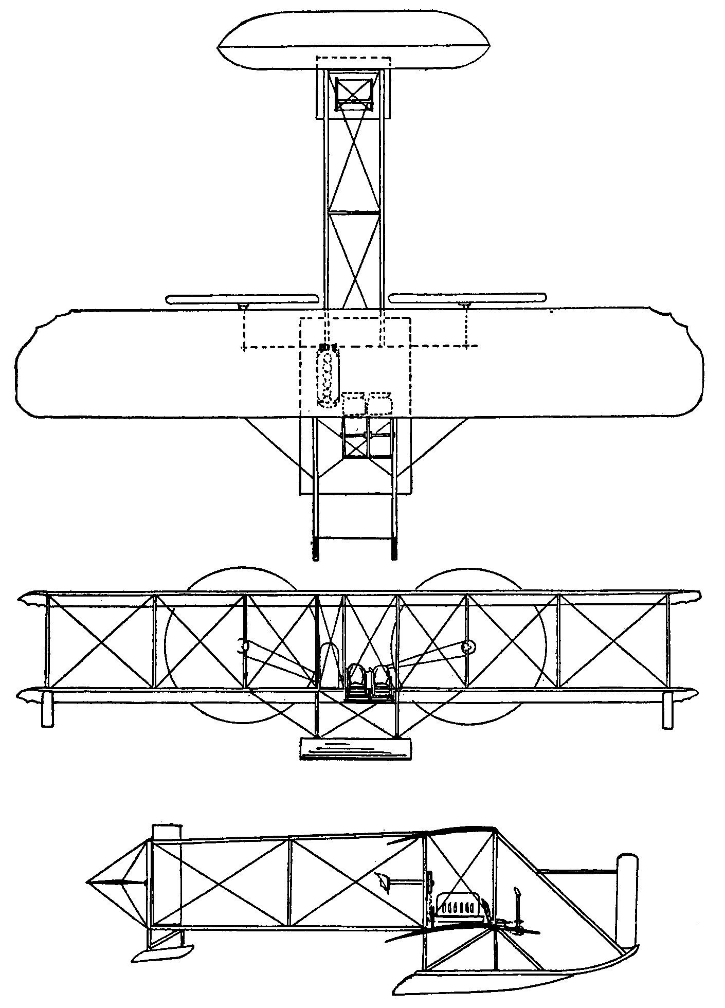
| 1903
Wright Flyer 1
The Wright brothers' first powered airplane had a 40.3-foot span; 0.83-foot anhedral; 6.5-foot chord; 6.2-foot separation; 510 sq-foot area; 1/20 camber; 48 sq-foot double horizontal front rudder; 21 sq-foot twin movable vertical rear rudders; 21.1-foot overall length; and weighed 605 lb. The right wing was 4 inches longer to compensate for extra weight of engine. |
 |
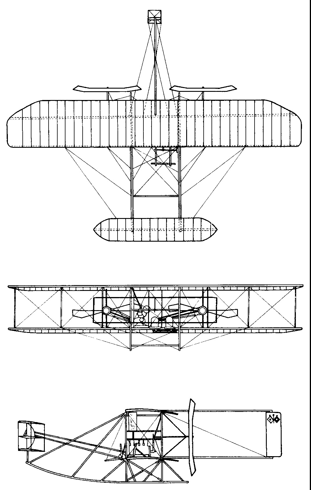
| 1905
Wright Flyer 3
The Flyer 3 was the first "practical" airplane, capable of flying and maneuvering as long as its fuel held out. The Flyer 3 had: 40.5-foot span; 6.5-foot chord; 6-foot separation; 503 sq-foot area; 1/20 camber; 83 sq-foot double horizontal front rudder ; 34.8 sq-foot twin movable vertical rear rudders; 28-foot overall length; and weighed 710 lb. |
 |
| 1907
Wright Model A
The Wright Model A were the first airplanes that the Wrights offered for sale. These biplanes had 41-foot span; 6.5-foot chord; 6-foot separation; 510 sq-foot area; 1/20 camber; 70 sq-foot double horizontal front rudder; 23 sq-foot twin movable vertical rear rudders; 31-foot overall length; and weighed 800 pounds. |
 |
| 1909
Wright Military Flyer
The Military Flyer, dubbed Miss Columbia, was the first airplane purchased by the United States Army Signal Corps. This biplane had a 36.5-foot span; 5.8-foot chord; 5-foot separation; 415 square-foot area; 80 sq-foot double horizontal front rudder ; 16 square-foot twin movable vertical rear rudders; 28.9-foot overall length; and weighed 735 lb. |
 |
| 1910
Wright Model B
The Wright Model B was the first Wright airplane with the elevator in the back. It had a 38.5-foot span; 6.2-foot chord; 5.3-foot separation; 1/20 camber; 500 sq-foot area; 40 sq-foot single flexible rear elevator; 15 sq-foot twin movable vertical rear rudders; 28-foot overall length; and weighed 1,250 lb. |
 |
| 1912
Wright Model C
The Wright Model C was an improved version of the Model B and had a more powerful motor. It had a 38-foot span; 440 sq-foot area; 6-foot chord; 5-foot separation, 29.8 feet length; and weighed about 1,090 lb. |
 |
| 1913
Wright Model CH
The Wright Model CH was a Model C mounted on pontoons for water landings and take-offs. (The "H" stood for "Hydro".) Its dimensions were the same as the Model C, although the pontoons increased its weight |
 |
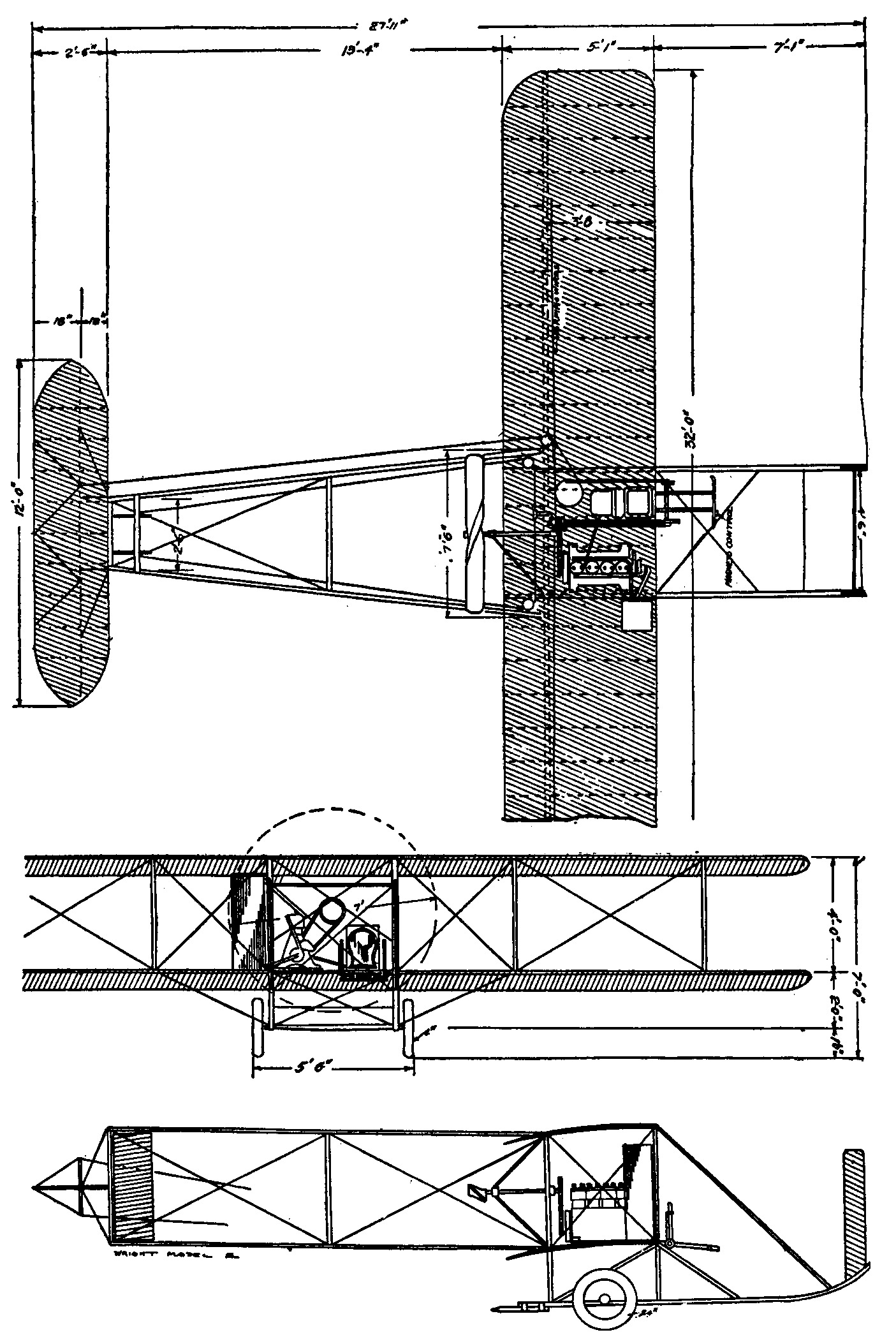
| 1913
Wright Model E
The Wright Model E was designed expressly for exhibition. It could be set up or packed away in a matter of minutes. This was the only Wright aircraft to have a single propeller. It had a 32-foot span; 316 sq-foot area; 5.1-foot chord; 27.9-foot length; and weighed about 730 pounds. |
 |
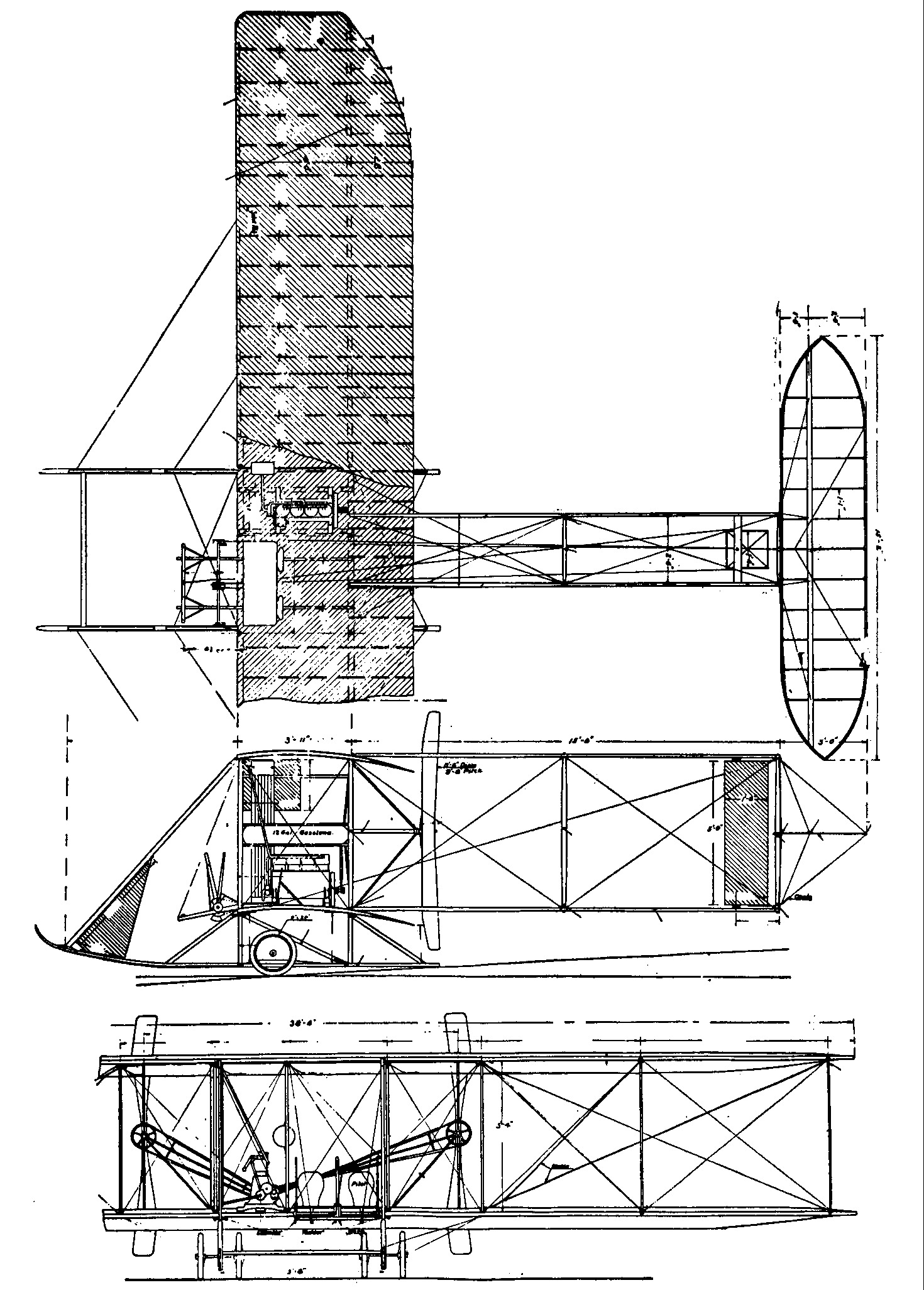
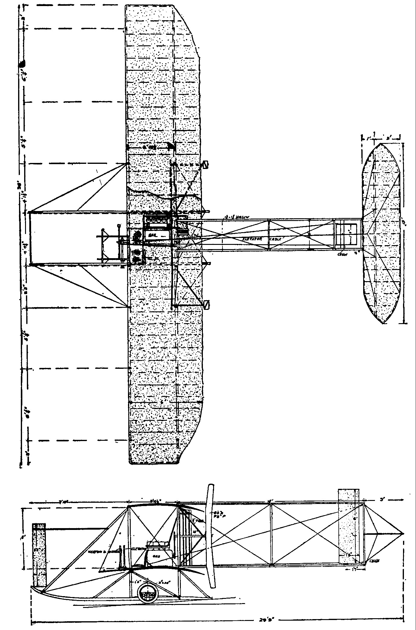
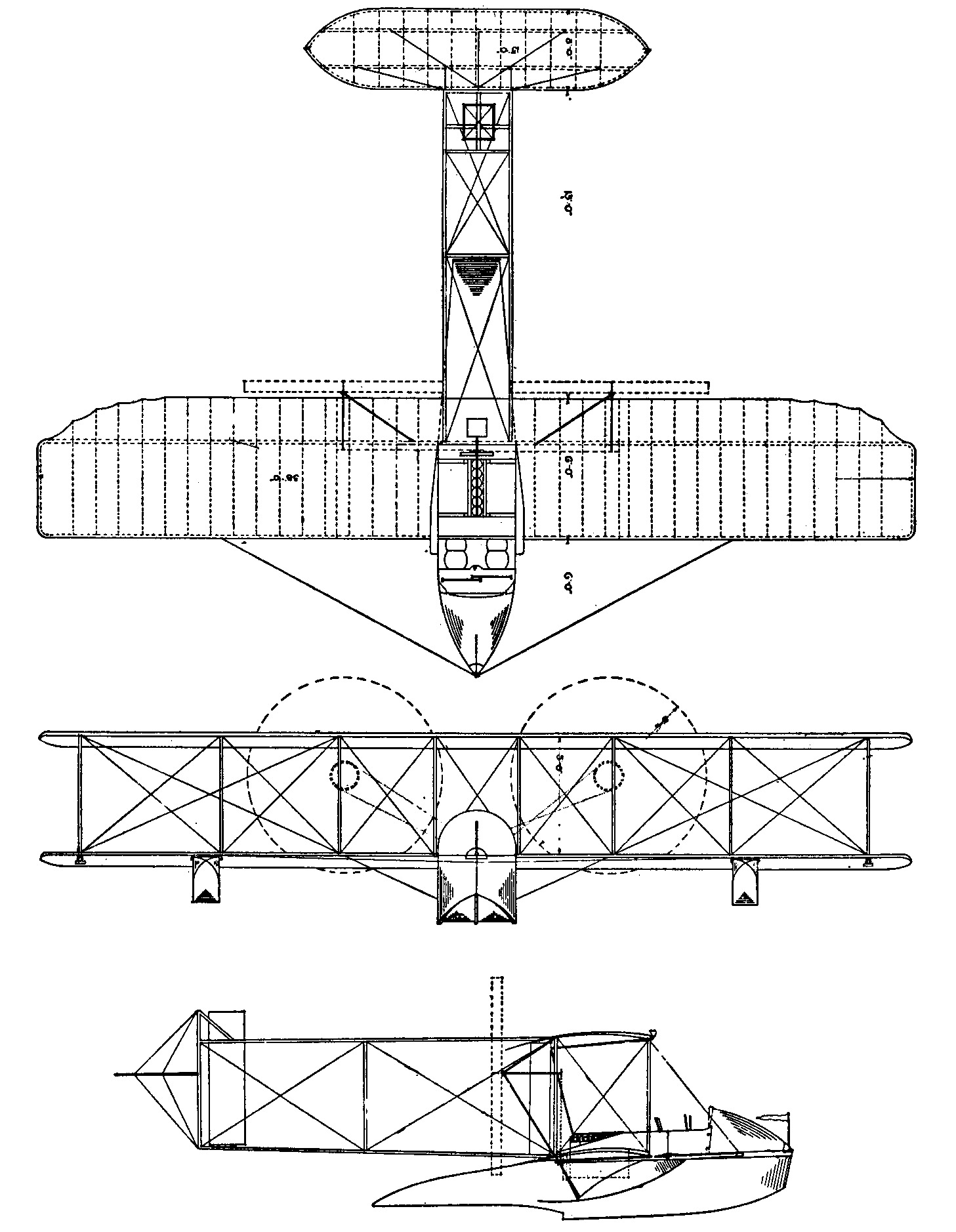
| 1913
Wright Model G
The Wright Model G was the Wrights only flying boat and their first airplane with an enclosed cockpit. It had a 38-foot span; 430 sq-foot area; 6-foot chord; 5-foot separation; 28 feet length; and weighed 1,200-1,300 pounds. |
 |
![]()
![]()
![]()